Comprehensive Analysis of Extruders: Working Principle, Classification, Structure, Application Industries, and Selection Guidelines
An extruder, fully known as a screw-type plastics extruder, is the core primary equipment in the field of polymer material processing. It is often hailed as the “machine tool of the plastics processing industry.” Its core principle is to use the rotational movement of the screw, combined with external heating from the barrel, to complete the conveying, compression, melting and plasticization, mixing and devolatilization of solid polymer materials. Ultimately, it continuously extrudes a uniform and stable molten material at constant pressure, flow rate, and temperature, which is then shaped by downstream dies and auxiliary equipment to form finished products.
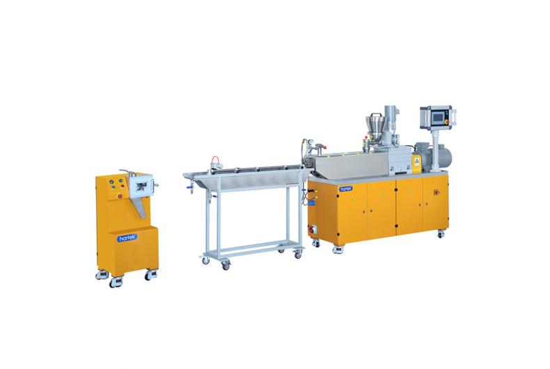
The extruder is the core power and plasticizing unit in a plastic extrusion production line. It is widely compatible with materials such as commodity plastics, engineering plastics, thermoplastic elastomers, and biodegradable plastics. It covers almost all thermoplastic processing scenarios, including pipes, profiles, films, sheets, wire and cable coating, pelletizing, and medical products. Over 80% of thermoplastic products worldwide are manufactured through extrusion processes.
I. Core Functions and Industry Value
The core value of the extruder extends throughout the entire process from solid polymer material to finished product. It is the key equipment that determines production line capacity, product quality, and production stability. Its core functions are as follows:
- Continuous conveying and pressurization of solid materials
Relying on the structural cooperation between the screw and the barrel, the extruder achieves positive-displacement conveying of solid materials. Simultaneously, it gradually builds up melt pressure, converting low-pressure solid materials into high-pressure, stable molten material. This provides sufficient molding pressure and stable flow for downstream dies, forming the basis for continuous production. - Uniform melting and plasticization of materials
Through the shear, compression, and friction generated by the rotating screw, combined with external heating from the barrel, solid plastic pellets or powders are completely melted. This achieves a uniform transition from the high-elastic state to the viscous-flow state, eliminating unmelted crystalline spots and uneven plasticization. This is a core step in ensuring product quality. - Efficient mixing and homogenization of multi-component materials
By optimizing the screw design, the extruder achieves efficient dispersion and distributive mixing of multiple components, such as the resin matrix with fillers, toughening agents, masterbatches, additives, and glass fibers. This ensures uniform distribution of composition, color, and performance throughout the material, making it the core equipment for plastic modification and compounding. - Devolatilization and venting
Vented extruders can remove moisture, residual monomers, low-molecular-weight volatiles, air, and other impurities from the material through a vacuum venting system. This prevents defects such as bubbles, shrinkage cavities, and silver streaks in the finished product, while also improving mechanical properties and environmental friendliness. It is suitable for processing recycled materials and high-moisture materials. - Precise closed-loop control of process parameters
Using high-precision sensors and control systems, the extruder achieves closed-loop control of melt temperature, pressure, flow rate, screw speed, and torque. This ensures process stability during extrusion, resulting in highly consistent dimensions and properties in mass-produced products, suitable for high-end precision manufacturing. - Expanding material processing boundaries
Through customized structural and process designs, extruders can adapt to difficult-to-process materials such as heat-sensitive, high-viscosity, highly filled, ultra-high-temperature specialty engineering plastics, and biodegradable plastics. They enable special processes like reactive extrusion, foam extrusion, and co-extrusion, thus expanding the application scenarios of polymer materials.
II. Basic Working Principle
The core working process of an extruder revolves around the rotational motion of the screw, combined with the barrel’s temperature control system, to complete the full conversion of material from solid to a uniform melt. The process is broadly divided into three working stages, accompanied by the synergistic effects of shear heat and external heating. The specific principles are as follows:
Three Core Working Stages (for conventional single-screw extruders)
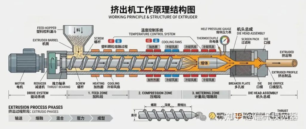
After plastic material enters the barrel from the hopper, it is conveyed axially along the screw channel as the screw rotates. It passes sequentially through three functional sections to complete the full plasticizing extrusion process:
- Feed Section (Solid Conveying Section): The starting section of the screw, with the deepest channel depth. Its core function is to receive and convey solid material while preheating and compacting it. The material remains solid in this section, is forced forward by friction between the screw and the barrel, gradually compacted into a solid plug, and simultaneously absorbs external heating from the barrel and a small amount of frictional heat, beginning to soften.
- Compression Section (Melting Section): The middle section of the screw, where the channel depth gradually decreases. Its core function is to compress, shear, and melt the compacted material. As the channel volume gradually decreases, the material is continuously pressurized. The strong shear between the screw, barrel, and material generates a large amount of viscous dissipation heat, which, combined with external heating, gradually melts the solid material. Complete melting is achieved at the end of the compression section, realizing the transition from solid to viscous-flow state.
- Metering Section (Homogenization Section): The end section of the screw, with the shallowest and constant channel depth. Its core function is to homogenize, stabilize pressure, and quantitatively convey the molten material. In this section, the fully molten material is further sheared and mixed to eliminate inhomogeneities in temperature, composition, and viscosity. Simultaneously, a stable melt pressure is established, and the material is finally delivered at constant flow rate, pressure, and temperature through the adapter to downstream screen changers and dies to complete the extrusion process.
Core Melting Principle
The melting and plasticization of plastics do not rely solely on external barrel heating. The core heat sources are divided into two parts:
- Shear Heat (Primary Heat Source): During screw rotation, the relative motion between the screw and the barrel generates strong shear and friction on the material, converting mechanical energy into thermal energy. This is the primary heat source for melting. Under high-speed extrusion conditions, shear heat can account for over 70% of the total heat, sometimes requiring cooling systems to remove excess heat.
- External Heating (Auxiliary Heat Source): Provided by heaters on the outer wall of the barrel, this is mainly used for preheating during startup and supplementing heat in low-temperature extrusion conditions to ensure the initial melting temperature and maintain melt temperature stability.
Pressure Build-up Principle
The melt pressure during extrusion originates from the gradual reduction of screw channel volume, the throttling resistance of the die, and the control of backflow through the clearance between the screw and barrel. As the screw rotates, material conveyed forward is resisted by the downstream die, gradually building up pressure. The shallow channel in the metering section restricts pressure backflow, ultimately achieving stable high-pressure melt output, providing the core power for die forming.
III. Core Classification and Structural Characteristics
The most mainstream classification in the industry is based on the number of screws and structural configuration. Different types of extruders have vastly different material compatibility, process adaptability, and application scenarios. The core classifications and technical features are as follows:
(I) Single-Screw Extruders
Single-screw extruders are the most basic and widely used machines in the industry. They consist of one screw and one barrel, offering simple structure, low cost, and easy maintenance. They are the workhorses for general extrusion molding. Based on screw structure and function, they can be subdivided into six types:
| Sub-type | Core Structural Features | Core Advantages & Disadvantages | Core Applicable Scenarios |
|---|---|---|---|
| Conventional Gradual-type Single-Screw | Three-section equidistant gradual screw; channel depth gradually decreases from feed to metering; extremely simple structure. | المزايا: Simple structure, low purchase and maintenance cost, easy operation, stable running. Disadvantages: Weak mixing ability, limited plasticizing efficiency, poor adaptability to different materials; unsuitable for highly filled or heat-sensitive materials. | General PE, PP pipe, film, sheet, cable sheath extrusion; low-requirement extrusion of virgin materials; small-to-medium capacity production lines. |
| Barrier-type Single-Screw | Barrier flight set in the melting section, separating unmelted solids from molten melt, forcing solids through barrier gaps for shear melting. | المزايا: High plasticizing efficiency, good melt uniformity, low pressure fluctuation, high output. Disadvantages: Difficult screw manufacturing, high shear, not suitable for strongly heat-sensitive materials. | High-speed extrusion lines, film, sheet, large-capacity general extrusion; applications requiring high plasticizing uniformity. |
| Separated-type (BM) Single-Screw | Additional secondary flight in the melting section, completely separating the solid bed and melt pool for separate conveying. | المزايا: Extremely high plasticizing efficiency, fast melting, precise temperature control, minimal pressure fluctuation, no unmelted particles. Disadvantages: Complex structure, high processing cost, limited adaptability to viscosity ranges. | High-end film, optical sheet, precision pipe extrusion; high-speed high-capacity lines; applications with strict requirements for gels and black specks. |
| Vented Single-Screw | Screw has a decompression section; barrel has a vacuum vent port connected to a vacuum pump; single or multiple venting stages. | المزايا: Online removal of moisture and volatiles without pre-drying; good plasticizing quality; suitable for high-moisture and recycled materials. Disadvantages: Complex structure, high screw design difficulty, higher cost than standard models. | Recycled plastic extrusion; processing of materials with high moisture content; PET, PA and other hygroscopic materials; prevents bubbles and silver streaks. |
| Pin-type Single-Screw | Pins installed on the barrel inner wall or screw channel to divide melt flow, enhancing shear and mixing. | المزايا: Much better mixing than conventional single-screw; good melt uniformity, precise temperature control, lower cost than twin-screw. Disadvantages: High shear, not suitable for strongly heat-sensitive materials. | Cable compounds, low-filled modified materials, rubber extrusion, sheet and plate production; general applications requiring some mixing. |
| Planetary Screw Extruder | Composed of a central main screw and multiple planetary screws that rotate around the main screw and also spin on their own axes within the barrel’s internal gear ring. | المزايا: Extremely high plasticizing efficiency, uniform shear, short material residence time, no dead zones, good self-cleaning. Disadvantages: Complex structure, high manufacturing precision required, high cost; not suitable for highly filled hard materials. | Processing of heat-sensitive materials (PVC, PMMA); sheet, plate, and calendering line feeding; food-grade material extrusion. |
(II) Twin-Screw Extruders
Twin-screw extruders consist of two parallel or conical intermeshing screws and a barrel. They rely on the intermeshing motion of the two screws to achieve positive-displacement conveying. Their mixing capacity, self-cleaning ability, and material adaptability are far superior to single-screw extruders, making them the core machines for plastic modification, difficult-to-process materials, and high-end molding.
Based on screw intermeshing mode, rotation direction, and structural form, they are divided into four main categories:
- Co-rotating Parallel Twin-Screw Extruder
- Core Structure: Two parallel screws of the same diameter rotating in the same direction. They can be closely intermeshing or non-intermeshing; the industry standard is closely intermeshing self-wiping type. The screws are of modular (building-block) design, allowing adjustment of conveying, mixing, and shearing capabilities by changing screw elements and kneading blocks.
- Core Advantages:
- Excellent self-cleaning ability; intermeshing flights wipe each other to prevent material buildup and carbonization, suitable for continuous production.
- Very strong mixing capability; modular elements allow flexible adjustment of shear intensity for efficient dispersion mixing of multi-component materials.
- Good conveying characteristics; positive-displacement conveying is strong, with wide material adaptability for powders, highly filled materials, glass-fiber reinforced, and heat-sensitive materials.
- Can accommodate multi-stage vacuum venting for good devolatilization, suitable for reactive extrusion and devolatilization modification.
- High speed, high output, high specific torque, and much higher production efficiency than single-screw.
- Disadvantages: Complex structure, high purchase and maintenance cost, more difficult operation; pressure stability in forming is weaker than counter-rotating twin-screw and single-screw.
- السيناريوهات القابلة للتطبيق: Plastic modification pelletizing, glass-fiber reinforcement, filling and blending, masterbatch production, reactive extrusion, devolatilization recycling, highly filled material processing – the absolute mainstay of the plastic modification industry.
- Counter-rotating Parallel Twin-Screw Extruder
- Core Structure: Two parallel screws rotating in opposite directions, either inward or outward intermeshing; the mainstream is inward intermeshing. Screws are mostly integral, with small intermeshing clearance and strong pressure-building capability.
- Core Advantages: Very strong positive-displacement conveying, uniform residence time, mild shear, far superior pressure-building capability than co-rotating twin-screw, stable extrusion pressure without pulsation.
- Disadvantages: Weaker self-cleaning than co-rotating, lower maximum speed, limited mixing capability, not suitable for high-shear modification processes.
- السيناريوهات القابلة للتطبيق: Direct extrusion of PVC powder; pipe, profile, and sheet production; continuous forming extrusion of low-shear heat-sensitive materials.
- Conical Twin-Screw Extruder
- Core Structure: Two conical intermeshing screws rotating in opposite directions; screw diameter gradually decreases from feed to metering section. Integral structure, with barrel and screw designed for conical fit.
- Core Advantages: Large diameter at feed section, large heat dissipation area, can accommodate more powder, strong conveying capability; compression ratio achieved through taper without variable channel depth, giving high screw strength; small diameter at the end, mild shear, strong pressure-building, suitable for heat-sensitive PVC powder processing; high torque with excellent low-speed high-torque characteristics.
- Disadvantages: Low maximum speed, limited mixing capability, difficult screw manufacturing, less versatility.
- السيناريوهات القابلة للتطبيق: PVC plastic-steel profiles, PVC pipes, PVC sheets, wood-plastic composite extrusion – the dedicated workhorse for PVC powder processing.
- Non-intermeshing Twin-Screw Extruder
- Core Structure: Two screws arranged non-intermeshing, with center distance greater than the sum of screw diameters; can be co-rotating or counter-rotating, similar to two parallel single-screws.
- Core Advantages: Long material residence time, large material capacity, can accommodate multi-stage venting for good devolatilization, suitable for high-volatile materials.
- Disadvantages: Poor self-cleaning, weak mixing, poor positive-displacement conveying, rarely used in industry.
- السيناريوهات القابلة للتطبيق: Special reactive extrusion, devolatilization of high-volatile materials, chemical recycling pretreatment of waste plastics, and other niche applications.
(III) Multi-Screw Extruders
Multi-screw extruders refer to those with three or more screws. The mainstream types are three-screw extruders and planetary screw extruders, mainly for special high-demand applications:
- Three-Screw Extruder: Three intermeshing co-rotating screws arranged in a triangular configuration, modular design. Compared to twin-screw, it has more intermeshing zones, more uniform shear, better mixing and dispersion, strong self-cleaning, shorter residence time, higher specific torque, and higher output. Suitable for high-end masterbatches, highly filled modifications, nanomaterial dispersion, and heat-sensitive material processing – an upgraded option in the modification industry.
- Four-Screw / Multi-Screw Extruders: Multiple screws arranged in a ring; mainly used for ultra-high-viscosity materials, reactive extrusion, and very large-scale devolatilization; extremely rare in industry, mostly custom-made for special applications.
(IV) Screwless Extruders
Screwless extruders do not rely on a screw for material conveying and plasticization. The mainstream type is the ram extruder, which uses a hydraulic cylinder-driven ram to compress and melt preheated material in the barrel, extruding it under high pressure.
- Core Advantages: Can establish extremely high extrusion pressure; no shear heat; suitable for difficult-to-melt, high-viscosity materials such as ultra-high-molecular-weight polyethylene (UHMWPE) and PTFE; stable forming pressure.
- Disadvantages: Non-continuous production (intermittent feeding and extrusion); low production efficiency; poor mixing capability.
- السيناريوهات القابلة للتطبيق: Extrusion of UHMWPE pipes and rods; specialty plastics like PTFE; laboratory high-pressure rheological testing.
IV. Core Structural Components of the Extruder
Regardless of type, the core functions of an extruder are realized by six major systems. The design, machining accuracy, and material selection of these systems directly determine equipment performance, service life, and operational stability. The core structures are detailed below:
1. Extrusion System (Core Working System)
The extrusion system is the heart of the extruder – the core site for material conveying, compression, melting, and mixing. It is often referred to as the “heart” of the extruder. Key components include the screw, barrel, hopper, adapter, and breaker plate.
(1) Screw
The screw is the most critical component of the extruder, directly determining plasticizing efficiency, mixing performance, extrusion capacity, and product quality.
- Material Selection:
- Standard conditions: 38CrMoAl nitrided steel, hardened and integrally nitrided, with surface hardness above HV900.
- High-wear/high-abrasion conditions: Bimetallic screws, with tungsten carbide or nickel-based alloy spray coating, offering 3–5 times higher wear resistance.
- Corrosion-resistant conditions: 316L stainless steel or Hastelloy.
- Core Structural Parameters:
- Screw Diameter (D): The nominal outer diameter of the screw thread, determining the extruder size. Common range: φ20 mm to φ300 mm, directly determining theoretical extrusion capacity.
- Length-to-Diameter Ratio (L/D): Ratio of effective screw working length to nominal diameter, determining plasticizing capability. Conventional single-screw: L/D = 20–30; high-efficiency single-screw: L/D = 30–40; twin-screw: L/D = 28–68. A larger L/D gives longer residence time and better plasticizing/mixing.
- Compression Ratio: Ratio of the volume of the first flight at the feed section to the volume of the last flight at the metering section, determining compression degree and plasticizing effect. Conventional single-screw: 2–5; crystalline plastics: 3–5; amorphous plastics: 2–3.
- Channel Depth: Determines material conveying and shear intensity. Shallower channels at the metering section give stronger shear, more stable melt pressure, and better plasticizing uniformity.
- Structural Type: Single-screws are mostly integral; twin-screws are predominantly modular, allowing flexible adjustment of conveying, shearing, and mixing capabilities by replacing conveying elements, kneading blocks, toothed discs, etc., to suit different materials and processes.
(2) Barrel
The barrel works with the screw as a pressure-bearing, heating, and wear-resistant component, forming a closed space for material conveying and plasticization.
- Material Selection:
- Standard: 38CrMoAl nitrided steel, integrally nitrided.
- High-wear: Bimetallic barrel with centrifugal cast wear-resistant alloy liner (2–3 mm thick, hardness HRC 58–64) for excellent wear and corrosion resistance.
- Vented barrels have vent ports; modular twin-screw barrels are segmented, with each section independently heated and cooled, allowing flexible length adjustment.
- Core Requirements: The radial clearance between the barrel inner bore and the screw should be controlled within 0.002–0.005 D. Excessive clearance increases melt backflow, reducing efficiency and plasticizing quality. The barrel must have high strength, high-temperature resistance, wear resistance, and corrosion resistance; hydraulic test pressure is 1.5 times rated working pressure with no leakage.
(3) Other Core Components
- Hopper: Gravity or forced-feed types; the core function is continuous and stable material supply to the barrel. Twin-screw extruders mainly use forced-feed systems to prevent powder bridging and ensure uniform feeding. Some hoppers have drying, heating, or stirring functions for hygroscopic or bridging-prone materials.
- Breaker Plate (Screen Pack Support): Installed at the barrel end; its core function is to convert the helical melt flow from the screw into straight flow, while supporting the screen packs and establishing back pressure to improve plasticizing uniformity. Typically made of high-strength stainless steel with uniformly distributed holes.
- Adapter: A transition component connecting the barrel to downstream screen changers and dies. Internal flow channels are designed with streamlined, dead-angle-free geometry to prevent material stagnation and carbonization, while ensuring smooth transition of melt pressure and flow.
2. Drive System
The drive system provides power for screw rotation, determining screw speed, torque, and operational stability. Core components include the drive motor, gearbox, coupling, and frequency/servo controller.
- Drive Motor: Mainstream is three-phase asynchronous AC motor with a frequency inverter for stepless speed control. High-end models use permanent-magnet synchronous servo motors for higher energy efficiency, better speed precision, faster response, and superior low-speed torque. Large-power models use DC motors or inverter-duty motors.
- Gearbox: Reduces motor speed and increases output torque – a core drive component. Mainstream is hard-faced helical gear reducers with high transmission efficiency, strong load capacity, low noise, and long service life. Twin-screw extruders use a special distribution gearbox to synchronously drive both screws and distribute torque, ensuring meshing accuracy.
- Transmission and Protection Components: Elastic or diaphragm couplings compensate for coaxiality deviations for smooth transmission. High-end models include torque limiters and overload protection to prevent equipment damage from screw jamming or material overloading.
3. Heating and Cooling System
The heating and cooling system controls material melting temperature and ensures plasticizing stability, directly determining melt temperature control accuracy and product quality.
- Heating System: Uses independent zone heating, axially divided into 3–12 heating zones along the barrel, each with independent temperature control. Standard heating methods: cast aluminum heaters, ceramic heaters; high-temperature conditions use cast copper heaters for high efficiency and temperature resistance. The barrel end and adapter have separate heating zones to maintain stable melt temperature.
- Cooling System: Removes excess shear heat to prevent material degradation and achieve precise closed-loop temperature control. Standard methods: air cooling (fan cooling) – simple, no leak risk, gentle cooling, suitable for single-screw; water cooling (circulating water) – fast cooling, high precision, suitable for twin-screw and high-speed extruders. High-end models use oil cooling for uniform cooling, no thermal stress, suitable for precision extrusion.
- Temperature Control Unit: Uses K-type/J-type thermocouples to collect temperature signals and PID intelligent controllers for closed-loop control, achieving accuracy of ±1°C. High-end models use fuzzy PID or adaptive algorithms for ±0.5°C accuracy, preventing material degradation and uneven plasticization due to temperature fluctuations.
4. Venting and Vacuum System
This is the core unit of vented extruders. It removes moisture, residual monomers, low-molecular-weight volatiles, air, and other impurities from the material, preventing bubbles, silver streaks, and shrinkage cavities in the final product.
- Core Structure: Vent ports are opened on the barrel corresponding to the screw decompression section, connected via piping to a vacuum pump. Mainstream pumps are water-ring vacuum pumps or Roots vacuum pumps, achieving vacuum levels above -0.095 MPa. Twin-screw extruders can have multiple vent ports for multi-stage devolatilization, giving better results.
- مبدأ العمل: In the decompression section, the screw channel depth suddenly increases, causing a rapid drop in melt pressure. Volatiles and moisture dissolved in the melt vaporize and are extracted by the vacuum pump, achieving online purification of the material without pre-drying, significantly improving production efficiency and product quality.
5. Measurement and Control System
The control system is the “brain” of the extruder, enabling real-time data acquisition, closed-loop control, safety protection, and full-line coordination, ensuring stable extrusion.
- Core Sensing Elements:
- Temperature sensors: Thermocouples/RTDs for real-time barrel, die, and melt temperature for closed-loop temperature control.
- Pressure sensors: High-temperature melt pressure sensors installed at the barrel end and die head, monitoring melt pressure – key indicator of plasticizing state and screen pack clogging, also providing overpressure alarms and shutdown.
- Torque sensor: Monitors screw output torque to prevent overload damage.
- Speed sensor: Monitors motor and screw speeds for closed-loop speed control.
- Control Unit:
- Standard models: PLC programmable controller + touchscreen HMI for setting temperature, speed, pressure, etc., displaying real-time status, with automatic temperature/speed control, fault alarms, and emergency stop.
- High-end models: Industrial computer control with recipe storage, process data traceability, remote monitoring, fault prediction; supports MODBUS, PROFINET, etc., to interface with downstream screen changers, melt pumps, haul-offs, winders, etc., for full-line automation.
- Multiple safety protections: over-temperature, over-pressure, overload, material starvation, oil leakage – automatic alarms and emergency shutdown to ensure equipment and personnel safety.
6. Auxiliary Equipment System
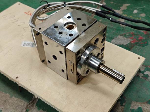
Extruders require downstream auxiliary equipment to complete the full product manufacturing process. Core auxiliaries include: screen changers (melt filters), melt pumps, forming dies, cooling/calibration units, haul-offs, cutters, winders/stackers, and online inspection equipment. The screen changer is a key auxiliary that ensures melt cleanliness and enables continuous production, perfectly matching the extruder.
V. Core Technical Parameters and Selection Guidelines
(I) Core Technical Parameters of Extruders
Selection is based on the equipment’s rated performance parameters, which must fully match material characteristics, production conditions, and capacity requirements. Core parameters are as follows:
| Parameter | Definition & Description | Typical Range |
|---|---|---|
| Nominal Screw Diameter | Nominal outer diameter of screw thread; determines size and theoretical capacity | Single-screw: φ20–φ300 mm; Twin-screw: φ20–φ135 mm |
| نسبة L/D | Ratio of effective length to diameter; determines plasticizing and mixing capability | Conventional single-screw: 20–30; High-efficiency: 30–40; Twin-screw: 28–68 |
| Rated Speed | Maximum continuous operating speed; determines capacity ceiling | Single-screw: 50–300 rpm; Co-rotating twin: 300–900 rpm; Counter-rotating twin: 10–60 rpm |
| Drive Power | Rated motor power; determines torque and load capacity | Small: 2.2–30 kW; Medium: 30–160 kW; Large: 160–1200 kW |
| Specific Torque | Twin-screw key parameter: torque per unit volume (Nm/cm³); indicates load capacity | General: 5–9; Medium-torque: 9–12; High-torque: 12–18 |
| Max Working Pressure | Maximum continuous melt pressure at barrel end; determines forming capability | Standard: 25–35 MPa; High-pressure: 35–50 MPa; Ultra-high ram: >100 MPa |
| Theoretical Output | Maximum theoretical capacity at rated speed (kg/h); actual varies with material/process | Small: 5–100 kg/h; Medium: 100–1000 kg/h; Large: 1000–10000 kg/h |
| Temperature Control Accuracy | Temperature deviation in barrel heating zones; determines melt temperature stability | Standard: ±1°C; High-end precision: ±0.5°C |
(II) Core Selection Guidelines
The core principles for extruder selection are: material compatibility first, capacity matching, process satisfaction, and reasonable cost – avoiding over-specification or under-specification. The specific selection steps are as follows:
Step 1: Determine the machine type based on material characteristics
Material characteristics are the primary basis for selection, directly determining the machine type. The core matching rules are:
| Material Type | Key Characteristics | Preferred Machine | Core Selection Requirements |
|---|---|---|---|
| General PE, PP, PS (polyolefins) | Easy melting, good flow, wide processing window | Conventional single-screw | L/D 25–30, gradual screw, compression ratio 2.5–4 |
| PVC (heat-sensitive) | Poor thermal stability, easy degradation, shear-sensitive | Counter-rotating conical twin-screw, planetary screw | Low shear, no dead zones, high temperature accuracy, avoid localized overheating |
| Engineering plastics (PC, PA, ABS, POM) | High melting temperature, hygroscopic, require high plasticizing uniformity | Vented single-screw, separated-type single-screw | L/D 30–35, single- or two-stage venting, temp accuracy ±1°C |
| Plastic modification, filling, blending, glass-fiber reinforcement | Multi-component, high filling, need strong mixing/dispersion | Co-rotating parallel twin-screw | Modular screw, L/D 40–56, high torque, multi-stage venting |
| Recycled/regrind plastics | High impurities, high moisture, variable properties | Vented single-screw, two-stage single/twin-screw | Multi-stage vacuum venting, large filtration area, strong mixing/homogenization |
| UHMWPE, PTFE | Difficult to melt, ultra-high viscosity, shear-sensitive | Ram extruder, specialized single-screw | Low shear, high-pressure forming, dedicated screw design |
| Biodegradable plastics (PLA, PBAT) | Heat-sensitive, hydrolyzable, hygroscopic | Vented single-screw, low-shear co-rotating twin-screw | Low shear, no stagnation, multi-stage venting, precise temperature control |
Step 2: Determine machine subtype based on product type and process
Different product forming processes have vastly different performance requirements for the extruder. Key matching rules:
- Pipe and profile extrusion: Prefer single-screw or counter-rotating twin-screw; require stable extrusion pressure, uniform flow, low pressure fluctuation; L/D 25–35, suitable for high-speed extrusion lines. PVC pipes/profiles: prefer conical twin-screw.
- Film, sheet, and plate extrusion: Prefer separated-type or barrier-type single-screw; require good plasticizing uniformity, precise temperature control, no gels or black specks; L/D 30–35; multi-layer co-extrusion requires multiple extruders.
- Wire and cable extrusion: Prefer conventional single-screw or pin-type single-screw; require high extrusion speed, stable pressure, uniform insulation thickness; L/D 25–30.
- Modification pelletizing and masterbatch production: Prefer co-rotating parallel twin-screw; require good mixing/dispersion, strong self-cleaning, high torque and high speed; L/D 40–56, with underwater or air-cooled die-face pelletizing.
- Precision medical and optical product extrusion: Prefer separated-type single-screw or precision co-rotating twin-screw; require no dead zones, high cleanliness, temperature accuracy ±0.5°C, materials compliant with FDA and GMP.
Step 3: Determine equipment size based on capacity requirements
- Determine target output (kg/h); select matching screw diameter and drive power based on material density and screw conveying efficiency.
- Actual output is typically 60–80% of theoretical capacity; reserve at least 20% margin to avoid continuous full-load operation.
- Drive power must match screw diameter, L/D, and material properties. Highly filled, high-viscosity materials require larger power and higher specific torque to avoid underpowering.
Step 4: Determine configuration based on automation needs and budget
- For small-to-medium capacity and general conditions, choose semi-automatic models with PLC + touchscreen – low cost, easy operation and maintenance.
- For 24/7 continuous production and high-end product lines, choose fully automatic intelligent models with full-line coordination, recipe storage, data traceability, and remote monitoring.
- For high-wear, high-corrosion conditions, choose bimetallic screws and barrels, stainless steel materials to extend service life.
- When budget is limited, prefer single-screw for general extrusion, and medium-torque co-rotating twin-screw for modification pelletizing – avoid over-configuration.
Key Selection Pitfalls to Avoid
- L/D ratio is not always better when larger; too long an L/D can cause excessive residence time and degradation of heat-sensitive materials – choose based on material properties.
- Twin-screw speed is not always better when higher; high-shear materials need lower speeds to avoid thermal degradation – focus on specific torque and load capacity.
- Drive power is not always better when higher; it must match screw diameter and material. Oversized power wastes energy; undersized power causes overload trips.
VI. Installation, Commissioning, and Full Lifecycle Maintenance Standards
(I) Core Installation Standards
- Before installation, prepare the foundation: concrete strength must meet requirements, reserve anchor bolt holes, ensure foundation levelness deviation ≤0.1 mm/m.
- After positioning the main machine, adjust levelness to ensure coaxiality between screw and barrel, preventing abnormal noise and wear during operation. Coaxiality deviation between gearbox and motor ≤0.05 mm to prevent coupling damage and bearing wear.
- Electrical installation: proper grounding with ground resistance ≤4Ω; keep away from strong electromagnetic interference; separate power and signal cables to avoid interference.
- Heating and cooling systems: heaters firmly fixed, thermocouples properly inserted, cooling water lines leak-free, vacuum pump lines well sealed with no leakage.
- Reserve sufficient operation and maintenance space; leave space at least equal to total screw length for screw removal; keep surroundings clear of obstacles.
(II) Standard Commissioning Steps
Pre-start inspection:
- Confirm screw and barrel properly installed, fasteners tightened; gearbox oil level normal; hydraulic oil, cooling water, air circuits normal; electrical connections correct, emergency stop and safety devices functional; heaters and thermocouples secure; temperature control system normal; downstream auxiliaries ready.
Stepwise preheating:
- Set barrel zone temperatures per process requirements; first heat to 150°C and hold for 30 minutes, then gradually raise to set processing temperature and hold for 1–2 hours to ensure uniform temperature throughout barrel and screw. Never start screw cold to avoid damage. For heat-sensitive materials like PVC, strictly control heating ramp and holding time to prevent degradation.
No-load trial run:
- After preheating, start the main motor at low speed (5–10 rpm) for no-load operation. Check smooth screw rotation, no abnormal noise or binding; motor and gearbox temperature rise normal; current and torque normal; control functions normal. Run no-load for 10–30 minutes without issues, then gradually increase speed to 30–50% of rated speed; after stability, proceed to load trial.
Load trial production:
- Start feeding system with low feed rate and low screw speed. After melt extrudes uniformly from the die, gradually increase screw speed and feed rate to normal operating conditions. Monitor melt temperature, pressure, motor current, torque in real time; check barrel for leakage; inspect product appearance. After 30 minutes of stable continuous operation with all parameters stable, proceed to formal production.
(III) Full Lifecycle Maintenance Standards
Daily Maintenance (Every Day)
- Before startup: check gearbox oil level, cooling water circuits, vacuum pump oil level; confirm no leaks or abnormalities.
- During production: monitor temperature, pressure, current, torque in real time; stop immediately if any abnormality is found.
- Check for abnormal noise, vibration, oil leakage; check fasteners for looseness.
- After each shift: clean external surfaces of oil and dust; clean residual material from hopper; maintain equipment cleanliness.
Weekly Maintenance
- Tighten loose heater connections and electrical terminals; check thermocouple and pressure sensor mounting.
- Clean cooling system filters, vacuum pump filters; remove scale from water lines to ensure cooling efficiency.
- Check feeding system operation; clean residual material from feed screw to prevent bridging or jamming.
- Check hydraulic and pneumatic system seals; tighten loose pipe joints; replace aged seals.
Monthly Maintenance
- Replace gearbox air filter; check lubricating oil condition – replace if emulsified or contaminated.
- Calibrate temperature sensors, pressure sensors, and temperature controllers to ensure measurement and control accuracy.
- Check screw and barrel wear by monitoring output and pressure changes to determine if clearance exceeds limits.
- Tighten all connection bolts; check coupling and bearing condition; replenish grease as needed.
- Clean vacuum pump and cooling system; replace vacuum pump oil and cooling water to ensure stable operation.
Annual Overhaul
- Fully disassemble equipment; withdraw screw; thoroughly clean barrel, screw, breaker plate, and die flow channels. Inspect screw and barrel for wear and scoring. Minor wear can be repaired by nitriding or spray coating; severe wear requires replacement.
- Fully disassemble gearbox and distribution box; clean gears and bearings; inspect wear; replace worn gears, bearings, oil seals; replace all lubricants.
- Replace aged heaters, wires, thermocouples, pressure sensors; overhaul electrical control system; upgrade control programs.
- Overhaul cooling, heating, vacuum, and drive systems; replace aged piping, seals, valves.
- After reassembly, re-calibrate levelness and coaxiality; perform hydraulic pressure test, no-load trial run, and load trial run to confirm all performance meets standards before putting back into production.
Long-term Shutdown Maintenance
- Before shutdown, use purging compound to thoroughly clean residual material from barrel, screw, and die flow channels to prevent carbonization from long-term stagnation.
- Turn off heating system; after equipment cools to room temperature, turn off cooling water, power, and air supply.
- Withdraw screw; clean and apply anti-rust oil; store vertically suspended to prevent deformation.
- Clean barrel inner wall, hopper, die; apply anti-rust oil; seal barrel ends, feed and discharge openings for dust, moisture, and rust protection.
- Drain oil from gearbox, vacuum pump, hydraulic station; clean internals; prepare for storage.
VII. Common Fault Diagnosis and Solutions
| Fault Phenomenon | Core Cause Analysis | Standard Solution |
|---|---|---|
| No output / insufficient output | 1. Hopper bridging, feed port clogged; material cannot enter barrel. 2. Feed section temperature too high, material melts and bridges prematurely. 3. Severe screw/barrel wear, excessive clearance causing backflow. 4. Feeding system failure, insufficient feed rate. 5. Screen pack/breaker plate severely clogged, high flow resistance. 6. Screw speed too low, conveying capacity insufficient. | 1. Clear hopper and feed port; use forced feeding for powders. 2. Lower feed section temperature; cool feed port to prevent premature melting. 3. Inspect and repair/replace worn screw/barrel. 4. Overhaul feeding system; adjust feed rate. 5. Replace screen pack; clean breaker plate. 6. Increase screw speed to rated range. |
| Excessive melt temperature / material degradation | 1. Barrel heating set too high, localized overheating. 2. Screw speed too high, excessive shear heat. 3. Screw compression ratio too high, excessive shear. 4. Too long residence time (L/D too large). 5. Temperature control system failure, inaccurate measurement, heating runaway. 6. Cooling system failure, unable to remove excess shear heat. | 1. Lower barrel heating temperatures; optimize temperature parameters. 2. Reduce screw speed to reduce shear heat. 3. Replace with lower compression ratio screw. 4. Reduce residence time by optimizing screw design and increasing feed rate. 5. Calibrate thermocouples and controllers; repair heating contactors. 6. Overhaul cooling system; clear water line blockages; increase cooling water flow. |
| Large melt pressure fluctuation / unstable output | 1. Uneven feeding (hopper bridging, feeding system failure). 2. Fluctuating barrel zone temperatures, uneven melting. 3. Screw/barrel wear, excessive clearance causing unstable backflow. 4. Screen pack clogging, large differential pressure fluctuation. 5. Poor screw design, unstable solid bed breakup, uneven melting. 6. Drive system failure, screw speed fluctuation. | 1. Resolve hopper bridging; overhaul feeding system for uniform feeding. 2. Optimize temperature control parameters; calibrate control system for stable temperatures. 3. Inspect and repair/replace worn screw/barrel. 4. Replace screen pack; consider automatic screen changer. 5. Optimize screw design; replace with barrier/separated-type screw for better melting stability. 6. Overhaul motor, inverter, gearbox for stable speed. |
| Black specks, gels, yellowing in product | 1. Poor plasticization, unmelted gels. 2. Dead zones in barrel, screw, or flow channels causing material stagnation and carbonization. 3. Screen pack ruptured, contaminants entering downstream. 4. Material degraded by overheating, yellowing. 5. Raw material impurities not effectively filtered. 6. Screw/barrel wear, metal particles entering melt. | 1. Optimize screw speed and temperature for better plasticization; replace with separated/barrier-type screw. 2. Disassemble and clean barrel, screw, flow channels; use streamlined dead-angle-free die design. 3. Replace screen pack; check support plate; use screen changer. 4. Lower processing temperature and screw speed to avoid degradation. 5. Pre-treat raw materials; increase screen layers and filtration precision. 6. Inspect and repair/replace worn screw/barrel. |
| Bubbles, silver streaks, shrinkage cavities | 1. High material moisture, not pre-dried, no venting system. 2. Vent port clogged, vacuum pump failure, insufficient vacuum. 3. Feed section temperature too high, air entrained with material. 4. Melt temperature too high, degradation producing volatiles. 5. Insufficient extrusion pressure, low die pressure, unable to expel gases. | 1. Pre-dry material; switch to vented extruder. 2. Clear vent port blockage; overhaul vacuum pump; increase vacuum level. 3. Lower feed section temperature; cool feed port to avoid air entrainment. 4. Reduce melt temperature and screw speed to avoid degradation. 5. Increase screen layers; raise die resistance to establish stable back pressure. |
| Abnormal screw noise / excessive vibration | 1. Poor coaxiality between screw and barrel; screw bent. 2. Severe screw/barrel wear, excessive clearance. 3. Metal foreign objects in barrel, screw jamming/scraping. 4. Gearbox or bearing wear/damage, loose transmission parts. 5. Coupling misalignment causing uneven transmission. 6. Screw speed too high, exceeding critical speed. | 1. Correct coaxiality; straighten bent screw. 2. Inspect and repair/replace worn screw/barrel. 3. Stop immediately; disassemble and remove foreign objects; inspect scratches. 4. Overhaul gearbox; replace worn bearings/gears. 5. Realign coupling; tighten loose fasteners. 6. Reduce screw speed to rated range; avoid exceeding critical speed. |
| Motor overload / tripping | 1. Screw speed too high, feed rate too high, load exceeds rating. 2. Material viscosity too high, screw torque excessive. 3. Barrel temperature too low, material not melted, high load. 4. Foreign objects in barrel causing screw jamming. 5. Screw/barrel clearance too small or assembly misalignment causing scraping. 6. Motor/inverter failure, electrical short circuit. | 1. Reduce screw speed and feed rate to keep load within rating. 2. Raise processing temperature to lower viscosity; switch to higher torque model. 3. Reheat and hold to ensure complete melting before starting. 4. Stop immediately; disassemble and remove foreign objects. 5. Check screw/barrel clearance; correct assembly coaxiality. 6. Overhaul motor, inverter, electrical circuits; eliminate faults. |
VIII. Main Application Fields and Dedicated Solutions
Plastic Modification and Pelletizing Industry
Largest application area for extruders. Core machine: co-rotating parallel twin-screw extruder, for filling, reinforcement, toughening, blending modification, masterbatch production, and waste plastic recycling pelletizing. For highly filled, high-output applications, use high-torque three-screw extruders; for heat-sensitive materials, use low-shear two-stage twin-screw extruders.
Plastic Pipe Extrusion Industry
- PE, PPR, PEX polyolefin pipes: core machine – high-efficiency single-screw extruder, L/D 30–35, high-speed stable extrusion with uniform wall thickness.
- PVC pipes and drainage pipes: core machine – counter-rotating conical twin-screw extruder, low shear, no degradation, suitable for direct PVC powder extrusion.
- Large-diameter gas pipes and municipal pipes: large-diameter single-screw extruder + multi-layer co-extrusion technology.
Plastic Profiles and Wood-Plastic Composites
- PVC plastic-steel window profiles, decorative profiles: core machine – counter-rotating conical twin-screw extruder.
- Wood-plastic composites, PE/PP profiles: single-screw or counter-rotating twin-screw extruder, strong mixing, high torque, suitable for high wood-flour filling.
Film and Sheet Industry
- General packaging film, cling film, cast film: core machine – separated-type/barrier-type single-screw extruder, uniform plasticization, no gels.
- Optical-grade film, BOPP/BOPET biaxially oriented film: high-precision single-screw extruder + multi-layer co-extrusion, temperature accuracy ±0.5°C.
- PVC, PET sheets and thick plates: planetary screw extruder or vented single-screw extruder, no stagnation, good devolatilization.
Wire and Cable Industry
- Power cable, communication cable, optical cable sheathing: core machine – conventional single-screw or pin-type single-screw, high speed, stable pressure.
- Cross-linked cable compounds, low-smoke halogen-free flame-retardant cable materials: two-stage unit (co-rotating twin-screw + single-screw), good mixing, suitable for highly filled flame-retardant materials.
Medical and Food-Grade Products
- Medical infusion tubes, syringes, food packaging containers: core machine – food/medical-grade dedicated single-screw extruder, 316L stainless steel, mirror-polished dead-angle-free flow channels, FDA/GMP compliant, with high-precision temperature control and clean extrusion systems.
Chemical Fiber Spinning Industry
- Polyester, nylon, polypropylene spinning: core machine – high-pressure high-precision single-screw extruder, stable melt pressure, uniform temperature, no gel particles, with high-precision filtration to ensure continuous spinning and prevent spinneret clogging.
Specialty Plastics and Advanced Process Fields
- UHMWPE, PTFE: dedicated ram or single-screw extruders.
- Biodegradable plastics: low-shear vented extruders.
- Supercritical fluid foam extrusion: dedicated co-rotating twin-screw.
- 3D printing filament production: high-precision single-screw extruder, ensuring filament diameter tolerance within ±0.05 mm.
IX. Industry Technology Development Trends
Intelligent and Unmanned Upgrades
Integration of AI algorithms, machine vision, and digital twin technology enables adaptive optimization, predictive maintenance, and fault warning for extrusion processes. Supports industrial internet remote monitoring and interfaces with factory MES/ERP systems, achieving fully unmanned “lights-out” production – a core industry direction.
High Efficiency, Energy Saving, and Low Carbon
Use of permanent-magnet synchronous servo motors and servo-hydraulic systems reduces energy consumption by over 30% compared to conventional models. Optimized screw and barrel structures improve plasticizing efficiency and reduce useless shear heat. New insulation heating technologies reduce heat loss, aligning with carbon peaking and neutrality goals.
High Precision and High Stability
Improved machining and control accuracy, using advanced algorithms like adaptive PID and model predictive control for high-precision closed-loop control of melt temperature, pressure, and flow. Suitable for ultra-clean, high-precision extrusion demands of high-end optical, medical, and precision electronic components.
Specialization and Customization
Development of dedicated machine types and screw structures for difficult-to-process materials such as specialty engineering plastics, biodegradable plastics, and ultra-high-molecular-weight polymers. Expansion of special processes like reactive extrusion, supercritical foam extrusion, in-situ polymerization extrusion, and co-extrusion to broaden application boundaries.
Green Environmental Protection and Circular Economy Adaptation
Development of high-devolatilization, strong-mixing dedicated extruders for high-value recycling of waste plastics. Research on reusable filtration systems and low-VOC emission technologies to reduce environmental pollution during production. Adapt to processing needs of biodegradable plastics to support green transformation of the plastics industry.
Integrated and Modular Design
Integration of the extruder with screen changers, melt pumps, dies, and downstream auxiliaries into a compact unit to shorten melt residence time, reduce energy consumption, and improve line compactness. Modular design allows quick change of screw elements and barrel sections to accommodate flexible, small-batch, multi-variety production.
New Materials and Process Applications
Use of new wear- and corrosion-resistant alloys and nano-coating technologies to extend screw and barrel service life. Application of 3D printing to manufacture special-shaped screw elements and flow-channel components, achieving dead-angle-free, low-resistance designs impossible with traditional machining. Development of high-speed, high-torque twin-screw technologies to increase output and mixing efficiency.